
Automotive Aerodynamics, Comparison With Windtunnel
Case - Automotive Aerodynamics, Comparison with Windtunnel
This case study shows how Aerotak™ simulated a car body with moving ground and rotating wheels, and accurately predicted the drag.
Objective
Prediction of the drag on the DrivAer car using CFD simulations and comparison with experimental wind tunnel tests performed by Heft et al. (2012).
Simulation setup
The experimental setup is simulated to allow for proper comparison by setting up a computational domain with an inlet (blue), an outlet (red), and a moving ground (yellow). Wheels are modelled using a Moving Reference Frame model applied with velocity corresponding to their rotational speed. To capture the turbulent flow structures, the simulation is run transient using the Spalart-Allmaras Delayed Detached Eddy Simulation (DDES) turbulence model, resolving the largest turbulent length scales in the flow.


Simulation results
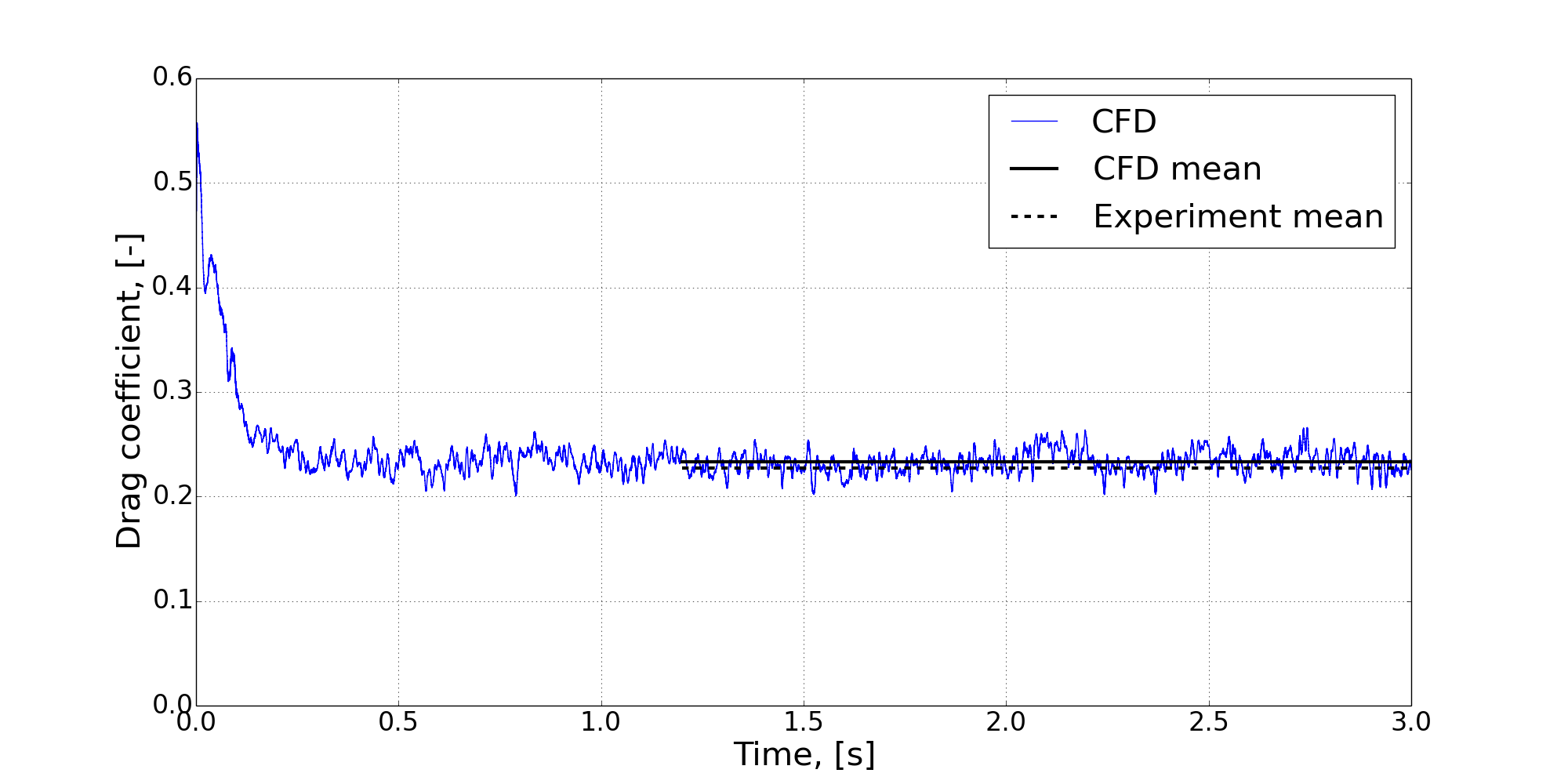
Comparing the CFD predicted drag coefficients to the experimentally obtained, shows a fine agreement with a discrepancy of 2,3% achieved after approximately 24 hours of simulation. The drag coefficient of the car, being the total drag on the car normalized by the air density, the velocity squared, and the cross-sectional area of the car, is measured throughout the transient simulation. The final mean drag coefficient is predicted on the basis of the temporally converged solution, obtained after ~1.7 physical seconds.
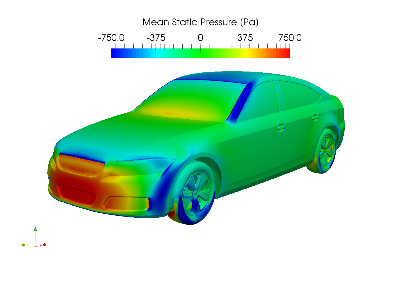
The predicted drag allows for readily validation of the simulation setup against benchmarking data. The validated model can be used to gain insight into the fluid over over the car as well as its aerodynamic characteristics. This can be done by studying e.g. the pressure distribution on and in the vicinity of the car. The figures below show mean static pressure on the car surface and mean velocity in a plane through the center of the domain.

The validated transient DDES model of the DrivAer car using a Moving Reference Frame model enables Aerotak™ to provide our customers with vehicle design optimisations, flow characterisation and understanding, along with relevant performance indicators such as drag, downforce etc. for any given car geometry.
For more information contact:

Kasper Berthu Damkjær
Managing Partner & Senior Fluid Mechanics Specialist
Phone: + 45 27 12 10 13
Mail: kbd@aerotak.dk
References
Heft, A.I, T. Indinger, and N.A. Adams 2012 “Introduction of a New Realistic Car Model for Aerodynamic Investigations”. Technische Universität München, SAE International.