
Spray Drying simulation
Case - Spray Drying simulation
This case study shows how Aerotak™ is able to simulate and map the flow field and particle trajectories within a commercial spray drying pilot plant fitted with a rotary atomizer.
Objective
Accurate prediction of particle paths, drying behavior, and estimation of product deposition on chamber walls. The overall purpose is to apply the CFD simulation as a tool for optimizing operating conditions and design to improve performance and product characteristics of a spray drying plant.
Simulation setup for a spray drying plant
The fluid domain is restricted to the spray drying chamber itself, consisting of a cylindrical part and a conical part transitioning to a bent outlet pipe. Downstream cyclone for product separation is not included in the fluid domain as well as the gas disperser located on top of the ceiling. The chamber is shown in Figure 1. The inlet annulus (marked in red) is provided with a set of velocity components for producing the drying air mass flow rate of 350 kg/h and the swirling conditions provided by the gas disperser. The inlet face is imposed with an absolute humidity and temperature corresponding to that of the operating condition. The outlet face (marked in blue) is imposed with a zero gauge pressure. All walls are imposed with a no-slip condition and a wall-to-ambient heat transfer coefficient to simulate the loss of energy due to convective heat transfer to the surroundings.
A k-omega SST turbulence model is adopted for turbulent flow structures and mixing between hot and cold regions of the chamber. Using a steady-state flow assumption on a volume mesh of 2 million cells, a fully developed flow solution is obtained prior to injection of computational parcels, representing droplets being atomized by the centrifugal atomizer. The atomization process is simplified by injecting particles composed of a liquid (evaporative) and a solid (non-evaporative) component. Parcels are imposed with an empirically estimated radial velocity component and a tangential velocity component equal to the peripherical speed of the rotary atomizer. Atomizer rotation is accounted for by applying a moving wall condition to the surface of the blunt atomizer geometry.
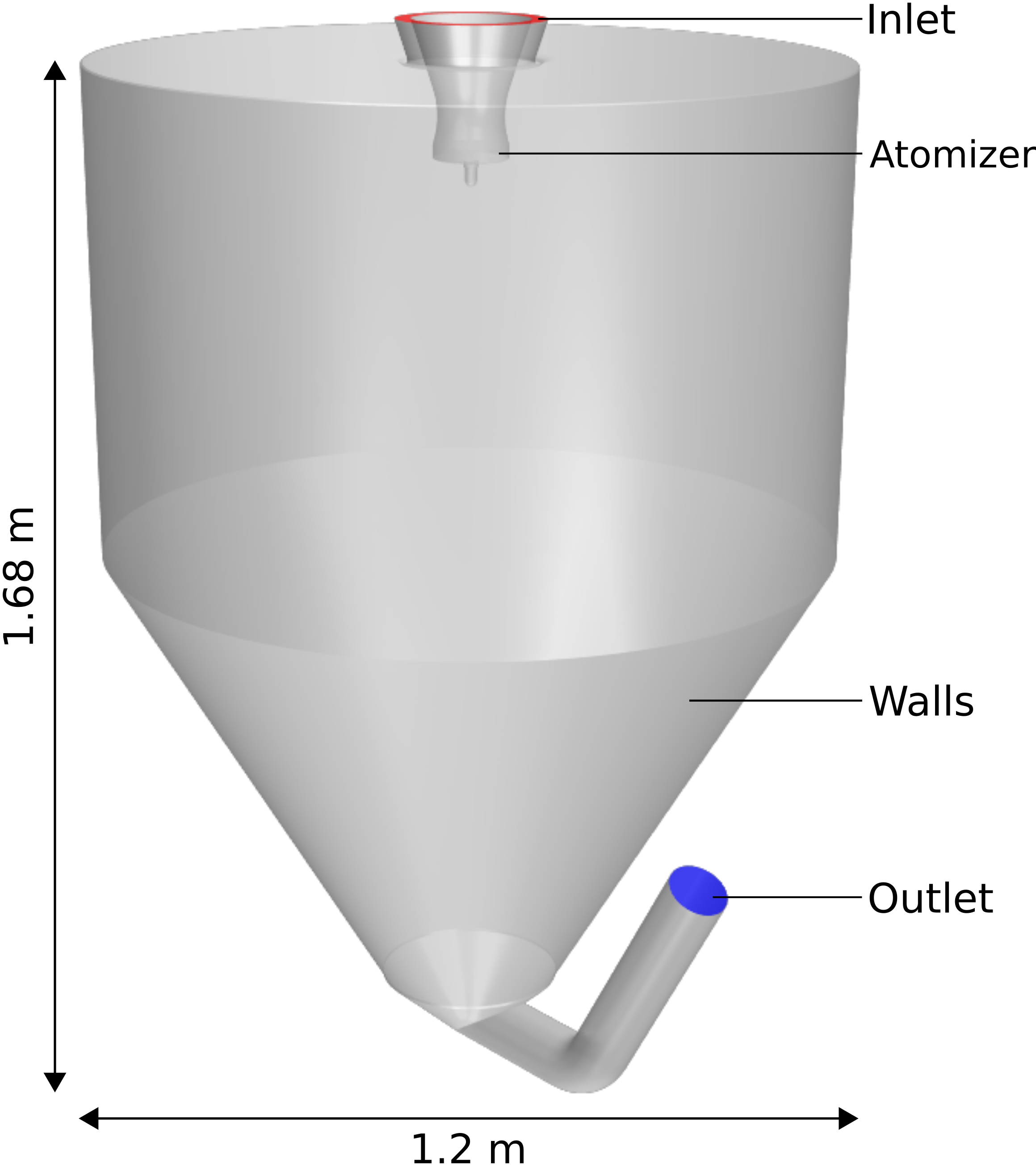
Figure 1
Spray drying simulation results
Converged flow and particle field results are obtained after 24 hours of simulation time. Flow and temperature fields are presented in Figures 2-3. A vertical plane through the geometric center of the chamber and six horizontal planes are used for vizualization. Variation in the temperature field influences the particle drying behavior, while the flow field is crucial for prediction of particle trajectories.

Figure 2

Figure 3
Instantaneous particle trajectories of individual parcels with residence time up to 0.1 seconds are plotted on the left hand side of Figure 4. An animation of the instantaneous particle tracks, covering the entire life span of the injected particles, is provided in Figure 5, with particles colored by residence time, truncated at 5 s. Maximum particle residence time of 20 s is found from the simulation.

Figure 4
Averaged particle statistics can be gathered to provide general information on trajectories, drying curves, residence times, mass flow rates etc. The right hand side of Figure 4 indicates averaged location and concentration of particles escaping the domain, with percentages expressing the particle mass weighted average residual moisture, which are directly related to wall deposition and its extent. For the current chamber configuration and operating condition, large particle impact rates on the cylindrical part of the cylinder are observed at high residual moistures, implying that wall deposition is likely to be most extensive in the upper part of the chamber.
Simulation of a spray drying process involving drying air, effect of atomizer rotation on air flow, drying behavior of injected particles, and monitoring of fluid properties throughout the system has been simulated by Aerotak™. The simulation technique can be applied for evaluating spray dryer designs of various sizes and configurations for improving performance and final product quality. The simulation allows for estimating wall deposition of semi-dried product, proving a valuable tool in prediction of product overheating, degrading, and risk of explosion. The simplicity, effectiveness, and efficiency of the setup enables the CFD tool to be applied in all stages of the design and construction phase to ensure reliable performance of the final dryer.
For more information contact:

Kristian Ingvorsen
Senior Fluid Mechanics Specialist
Phone: + 45 25 88 43 25
Mail: kmi@aerotak.dk